Object Follower Robot
Hi,
I'm Saksham from Lucknow, India and here is my newly made 'object follower Robot'.
It all started late in 2011 when I joined the 'BrainCafe Robotics Workshop'. During the workshop we were taught building simple robots including robots like object follower, object avoider, clap controlled etc. However the working of the robot was not explained to us properly. We simply wired up the sensors on the main board using berg connectors and the robot was good to go.
So now, after 3 long years I pulled out that robotics kit once again and modified it to work better.
Here are the differences between the modified robot and what the kit included-
- The simple transistor based 'main board', which the kit included, has been replaced by the Arduino Uno micro controller which behaves according to a program, written using a computer.
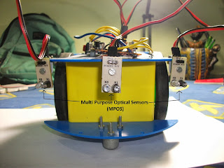
- The kit included 2 optical sensors i.e. left and right. However I have added another sensor in the middle for better results.
- The motor driver circuit gives full power of 9 volts to the motors. As a result, the robot moves faster.
- In the near future, I will be modifying the motor driver circuit to turn the wheels in both the directions, i.e. clockwise and anticlockwise both. As a result, the robot will be able to take sharper turns as well as move backwards.
Working-
Each sensor has a photodiode and a red LED. The light rays are emitted from the red LED which are reflected by the object infront of it. Some of the reflected rays strike the photodiode which sends an ON signal (1) through the output pin of the sensor to the microcontroller. If no object is infront of it, the light rays continue without reaching the photodiode and so an OFF signal (0) is sent to the microcontroller.
The microcontroller is programmed to digitally read the sensors' signals and control the motor driver circuit accordingly. The motor driver circuit finally makes the motors move.
The microcontroller is programmed to digitally read the sensors' signals and control the motor driver circuit accordingly. The motor driver circuit finally makes the motors move.
The Program:
int left,mid,right;
int leftmtr=3,rightmtr=5;
void setup(){
pinMode(leftmtr,OUTPUT);
pinMode(rightmtr,OUTPUT);
pinMode(A0,INPUT);
pinMode(A1,INPUT);
pinMode(A2,INPUT);
}
void loop(){
left = !digitalRead(A0);
right = !digitalRead(A2);
mid = !digitalRead(A1);
if (left==1&& right ==0 && mid==0)
{
digitalWrite(rightmtr,1);
digitalWrite(leftmtr,0);
}
else if (left==0&& right ==1 && mid==0)
{
digitalWrite(rightmtr,0);
digitalWrite(leftmtr,1);
}
else if (left==0&& right ==0 && mid==1)
{
digitalWrite(rightmtr,0);
digitalWrite(leftmtr,0);
}
else if (left==1&& right ==0 && mid==1)
{
digitalWrite(rightmtr,0);
digitalWrite(leftmtr,0);
}
else if (left==0&& right ==1 && mid==1)
{
digitalWrite(rightmtr,0);
digitalWrite(leftmtr,0);
}
else if (left==1&& right ==1 && mid==0)
{
digitalWrite(rightmtr,1);
digitalWrite(leftmtr,0);
}
else if (left==1&& right ==1 && mid==1)
{
digitalWrite(rightmtr,0);
digitalWrite(leftmtr,0);
}
else if (left==0&& right ==0 && mid==0)
{
digitalWrite(rightmtr,1);
digitalWrite(leftmtr,1);
}
}
Video coming soon...


Comments
Post a Comment